BIONIC WRENCH
REVERSE ENGINEERING A PRODUCT FOR MANUFACTURING OPTIMIZATION
Theis project explores various manufacturing engineering topics, including production system design, assembly, unit manufacturing processes, material handling, and optimization.
Client
Year
Location
CHICAGO
NORTHWESTERN
2023
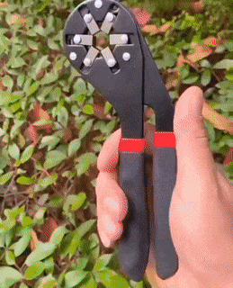
The BIONIC WRENCH is a tool by loggerhead tools capable of adapting to the size of the fastener
How can we reverse engineer a commercial product?
1ST PHASE: create a functional prototype
1
disassemble
2
measure
3
CAD
4
prototype
-
Disassemble wrench to its components
-
Document all components
-
Identify materials and manufacturing
-
Access accuracy needed for function
-
Utilize calipers, micrometer, gauges, optical comparators as needed
-
Use measurements to develop a 3D model and assembly on SolidWorks
-
Laser cut acrylic plates
-
Use standard fasteners to test prototype and iterate measurements
Disassemble & Document
To understand the product we decomposed it to its core elements and documented it.
A spectrometer was used to determine metal composition and expert's opinion was requested to determine coatings.
Research and field knowledge was applied to determine manufacturing.


Measurements
Depending on the accuracy needed, different measurement tools were used such as a micrometer and an optical comparator
CAD & Prototype
A 3D CAD model and assembly was developed using SOLIDWORKS.
Multiple prototypes, created using lasercut acrylic and standard fasteners, were used to test the quality of the measurements.

2ND PHASE: develop an assembly line
1
fixture design
2
production line
3
documentation
-
Create value stream map
-
Design fixtures for assembly line
-
Manufacture prototypes
-
Test fixtures
-
Design Production Line for optimal cycle time
-
Establiesh Worker SOP
-
Compile Product Documentation, BOM, Quality Standards, Worker SOP, Value Stream Map and Production line Design
Fixture Design
Through our understanding of the product we divided the assembly across 3 fixtures, initially made in acrylic and plywood and the final prototypes in stainless steel.
Fixture 1:
-
Inner plate assembly
-
Inner plate riveting
Fixture 2:
-
Inner and outter plate assembly
-
Inner and outter plate riveting
Fixture 3:
-
Jaw assembly
-
Jaw riveting


Production Line

